
When design engineers talk about “the weak link” in a power stack, they rarely point at the resistor—until it fails. A cracked element, a drifting value or a hotspot that exceeds 105 °C can shut down an inverter, a medical X-ray generator or a wind-turbine pitch controller in seconds. The new generation of thick-film planar power resistors was created precisely to erase that weak link. Rated at 300 W yet no larger than a cigarette pack, the technology combines five engineering breakthroughs that deserve a closer look.
Thick-film magic on an aluminium substrate Traditional wire-wounds rely on a helical coil that acts like an air-core inductor. By screen-printing a resistive paste directly onto an anodised Al₂O₃ plate, the path of current becomes a flat meander with almost zero self-inductance. Measured values stay below 80 nH up to 1 MHz—an order of magnitude lower than a comparable 300 W wire-wound part. That matters when you switch SiC or GaN transistors in nanoseconds: every nano-Henry saved reduces voltage overshoot and EMI.
Pulse muscles—1500 A for 1 ms without sweat Because the resistive layer is only 25 µm thick, heat leaves the “hot spot” laterally within microseconds. The result is an exceptional single-shot energy rating of 10 kJ and a peak current capability of 1500 A on millisecond pulses. In real life that translates into reliable crow-bar discharge, capacitor pre-charge or brake-chopper service where film or composition resistors would fracture after a few hundred shots.
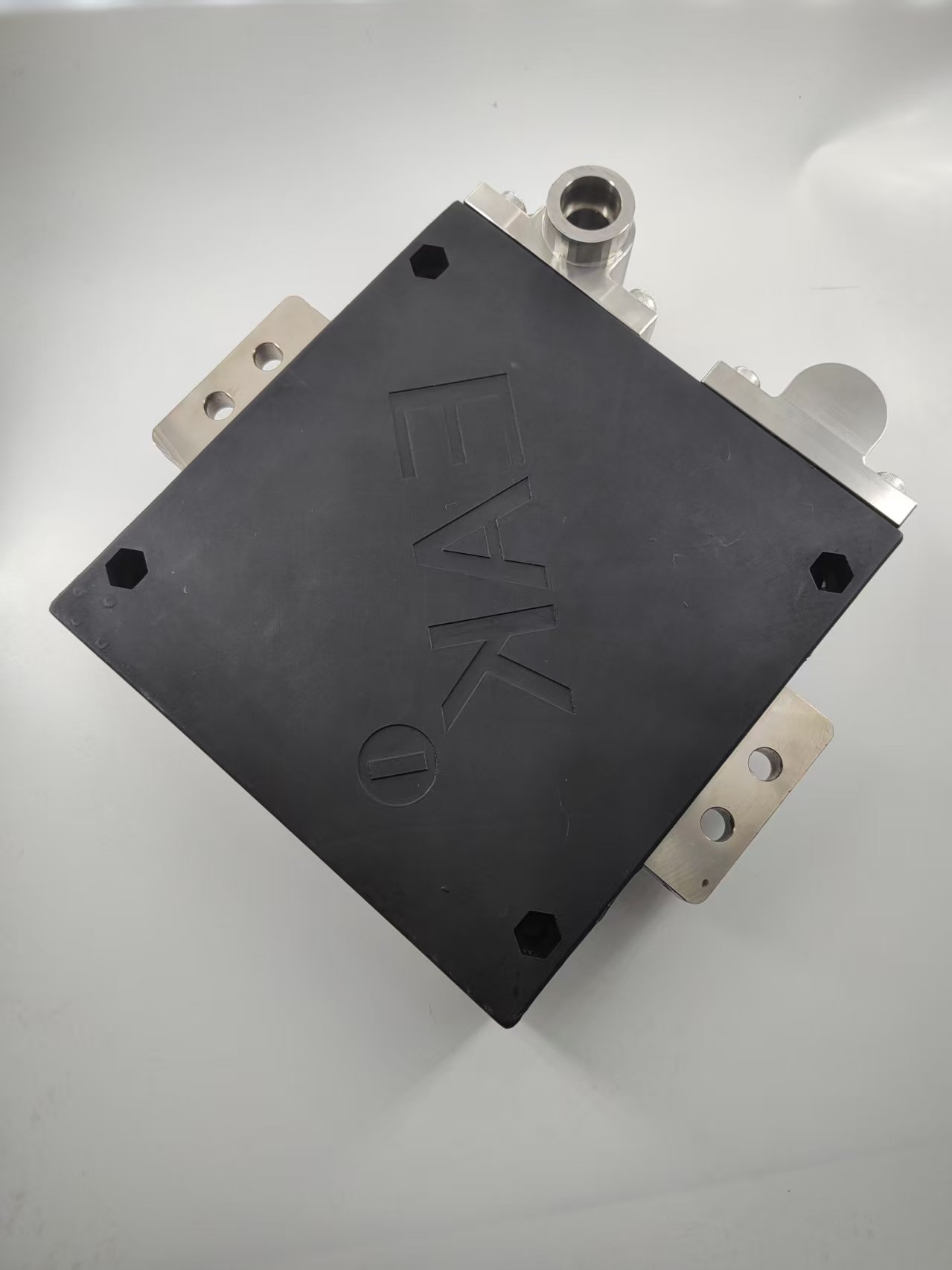
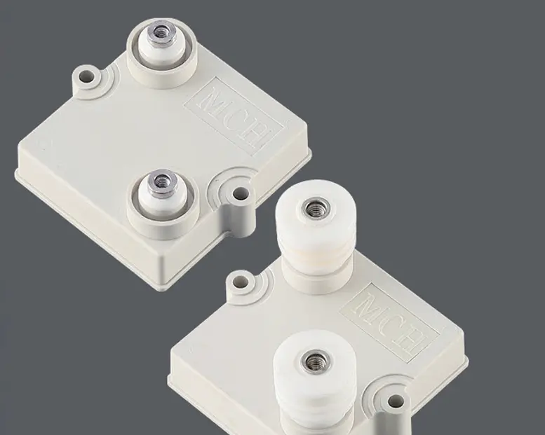
Cooler operation = longer life The planar construction is bonded to a 2 mm aluminium heat spreader that accepts a simple M4 screw. With only 0.5 K/W interface resistance, the device keeps the resistive film below 85 °C while dissipating full rated power, provided the back plate is fastened to a 300 cm² steel panel or a modest heat sink. Life tests at 1000 h, 70 °C base temperature show resistance drift ≤ 0.25 %—good news for preventive-maintenance schedules in remote solar farms or offshore substations.
6 kVrms isolation in a 4 mm profile Need to hang the resistor directly across a 1500 VDC bus? No problem. The alumina layer withstands 6 kVrms, 50 Hz for one minute and offers a 10 GΩ insulation resistance at 500 V. Partial discharge extinction voltage is above 2 kV, so corona cannot eat the edges even at 2 kVDC working altitude. That makes the part ideal for multi-level inverters, HVDC taps or medical X-ray tank circuits where space is tight but safety rules are tightest.
±150 ppm/°C and laser-trimmed tolerance Despite its brute power, the device is still a precision component. Laser trimming after sintering guarantees ±5 % standard tolerance (±1 % on request) and the TCR of the RuO₂-based ink is limited to ±150 ppm/°C from 25 °C to 105 °C. When you stack eight of them in a voltage divider for a 3000 V bus measurement, the divider drift stays below 0.3 % over the entire industrial temperature range, outperforming many metal-foil networks.
Typical applications that already benefit
Wind-turbine brake choppers: 200 kW crow-bar for 5 s, ambient –40 °C.
EV fast-charger pre-load: 1500 VDC, 50 A inrush, 100 ms, 1 Hz repetition.
MRI gradient driver: 300 W continuous, <80 nH for 100 kHz switching, class-B insulation.
HVDC tap resistor: 10 kV working, 3 kV transient, 95 % humidity, 40 °C, 56 days.
Mounting tips for maximum reliability
Use the recommended 1.8 Nm torque on the M4 screw and a minimum 1 mm layer of silicone-free heat-sink paste.
Allow 5 mm air gap around the edges; do not pot the entire body—keep the sidewalls open for convection.
When two or more resistors share the same heat sink, stagger them so that hot air from the upstream device does not pre-heat the downstream one.
For pulse service, calculate the temperature rise with the provided energy curve; if the duty cycle exceeds 5 %, add forced air or liquid cooling.
Future-proofing your design Wide-band-gap semiconductors are pushing switching frequencies beyond 100 kHz and DC buses towards 1500 V. A resistor that looks “over-spec” today may be barely adequate tomorrow. Choosing a thick-film planar power resistor rated 300 W, 6 kV, 1500 A gives you headroom on all three axes—power, voltage and pulse—without paying the size or inductance penalty of traditional solutions.
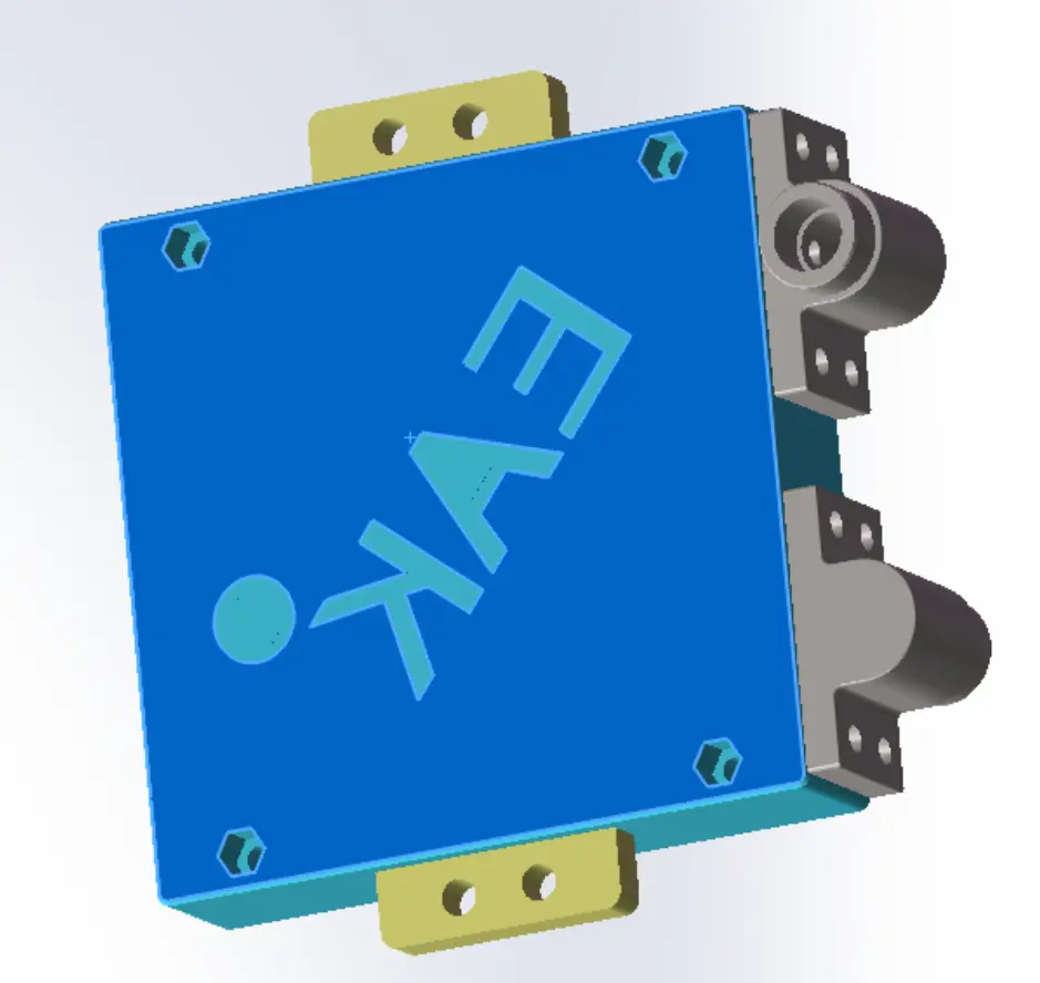
Ready to drop it into your stack? The footprint is 51 mm × 26 mm with two M4 inserts on 40 mm centres—drop-in compatible with most TO-247 or 63 mm hockey-puck brake resistors. Standard values run from 1 Ω to 1 MΩ, but custom prints down to 0.5 Ω or up to 50 MΩ are available with only a two-week lead time. Ask for the 150 ppm TCR option if your ambient swings are wide, or the 1 % tolerance version when the divider accuracy sets the system precision.
Conclusion Size, weight and reliability dominate every modern power-electronics roadmap. A thick-film planar power resistor that packs 300 W into 20 g, survives multi-kilovolt surges and stays cool enough to meet 20-year-field expectations is no longer a niche component—it is the new baseline for engineers who refuse to let the resistor become the weak link.